Syringe Hydraulic Arm PDF – Download in PDF Format
Like working with gears, pulleys, or levers; a mechanical advantage can be realized by using different size cylinders on the end of the hydraulic connections. By trading distance moved with the amount of force the advantage is realized.
 |
 |
|
| Moving the larger cylinder between 1 mark moved the smaller cylinder 2 marks. | Hydraulic cylinders for lifting and tilting bucket are easily seen in this tractor my father constructed. |
The story of my father’s company Champall Manufacturing in a 25 minute video. I created this several years ago as a DVD, not the best narration but an interesting story.
History of Champall Manufacturing – Link to YouTube video
Testimonial to Popularity of the Project
|
Sandy Gady 7th and 8th grade Math,Science, Design and Engineering teacher
“I have done the hydraulic arms with the syringes, they are so cool it’s beyond description. I used to do them when I taught 6th grade in a small town. We had lots of retired people with saws, so they would cut up the wood we needed. I then enlisted several of them to come into the classroom and we taught kids how to use drills, screwdrivers and hammers to assemble the finished project. In the end, they had a hydraulic arm that moved in three directions. I’ve had contact with some of these students since, and many of them still have their hydraulic arms 20 years later. They still beam with pride when they talk about them. Cost of materials, about $5.00. Educational value, priceless”. |
|||
 |
 |
|
| FuelMyBrain kids built a slightly different version of the hydraulic arm. | Large flat container was used to hold water to fill the hydraulic arms. |
Jump Down to Additional Syringe Experiment
 |
 |
|
|
The tubing I used was the type used for
aquarium airlines. Fuel line for model glow engines would work but is more expensive. There could be medical sources also. Then I found 1/8″ ID x 3/16″ OD tubing at a Fleet Farm store which is a tight fit. |
Syringes can be purchased where farm supplies are sold. I used the 12cc size as the pump and the 6cc size as the actuator cylinder. |
 |
 |
|
|
I used one flat washer on the pivot point of the gripper part of the arm, not sure it is needed.
|
8/32 Machine screws were used to hold clamps on and for pivot points. |
 |
 |
|
| I used these copper plated ½” tube straps to fasten the actuators (syringes) to the wood. |
The upright part of the arm is a furring strip. This inexpensive wood is used when installing drywall.
|
 |
 |
|
| For the horizontal part of the arm, I used 5/8” square stock that comes in 36” lengths. Normally found next to the round dowels. | Two sizes of craft sticks are used in this project, one on top is the size of a tongue depressor and the bottom one is the size of a Popsicle stick. |
 |
|
|
The base can be made from scrap boards also, best to pick out the better boards as some are warped. This board was labeled as 1” x 6” but true dimension was smaller.
|
Making Up the Parts
Normally I am making up kits for a class, so I will get all the parts fabricated first. That way few tools are needed to complete the project and it is safer for them not having to use saws or drills.
 |
 |
|
| Straighten the bend in the straps with a pliers. | The straps should look like this after 90 degree bends have been removed. |
 |
 |
|
| Cut the furring strip to 8 ½” in length. | Cut the 5/8” square stock to 11” in length. |
 |
 |
|||
| Cut 1” from both ends of craft stick, the ends are used for building gripper parts and the center is used to connect syringe to pushrods. |
|
 |
 |
|
| A “right triangle” is cut from scrap wood that is at least ¼” thick. The long side is 1 ½” long and shorter side is ¾” long. |
These are the wood parts needed before drilling the holes. The small triangle piece can be made from a scrap piece of ¼” wood.
|
Construction
 |
 |
|
| Drill holes for bearing pieces on the boom, I drilled both pieces together. | Bearing pieces after drilling the two holes at once. |
 |
 |
|
| Drilling the two holes on boom to mount the actuator (syringe). There is also a hole at the far right that is the pivot for this portion of the arm. |
Drilling hole at end for gripper assembly, this is drilled 90 degrees from the other holes. |
 |
 |
|
| Hole for strap on the main support is close to the edge so be especially careful when drilling. | Larger holes on the ends are pivot point and smaller holes in the middle is where pushrod attaches. |
 |
 |
|
| The pushrods for the gripper section can be made from paper clips that are straightened. Bend the curves out with your fingers and further straighten with a pliers. | One end of the pushrods will attach to the wood by making two 90 degree bends in the wire. Pictures shows the first bend, for this bending a needle nose pliers is needed. |
 |
 |
|
| Make another bend a short distance from the previous bend in the opposite direction. |
This is what the pushrod should look like, two will be needed. I was going to use music wire which is stiffer but it is also harder to bend.
|
 |
|||
|
 |
 |
|
| Mounting the actuator to lift the arm. I find it easier to test the fit of all pieces before gluing the wood wedge. |
Actuator to lift the boom is securely strapped at the correct angle. I should have mounted this slightly higher.
|
 |
 |
|
| The straps need to be pulled over the syringe very tight so that it does not shift when pressure is applied. |
Using two nuts tightened against each other should allow the nut to
the inside to have a small gap from the wood and not come off. The two thin pieces of wood need to turn freely on the bolt. |
 |
 |
|
| To position the two craft sticks that will be part of arm bearing make sure that the arm will come down to where the actuator is almost pushed in. |
Also make sure the arm can swing upwards without the binding at the hinge location. |
 |
 |
|||
|
Syringe actuator in extended position should lift arm above horizontal position. |
 |
 |
|
| I built the two halves of the gripper using Duco cement so I used clothespin to hold parts together while glue dries when possible. | The pads are added next, no real way to clamp it but the Duco is sticky at the start and tends to hold pieces together. |
 |
 |
|||
| Note washer on the bolt at the pivot point should help the wood parts move easier. Do not tighten the head of the bolt down too tight, the parts must be free to move easily. |
|
 |
 |
|
|
The wood piece with plastic tubes is glued
to the end of the syringe actuator. Hot glue holds fairly well or you can use small wood screws to attach the wood to the end of the syringe. |
Bring the gripper plates together, pull the actuator out to almost full extension, and insert the pushrod ends with the 90 degree bends into the small holes. |
 |
 |
|
| Bend the wire 90 degrees downward into the plastic tubes. |
Carefully bend the wire back so the pushrods do not
fall out. I was going to use music wire which would have been stiffer but the paper clip material is much easier to bend. |
 |
 |
|||||
|
|
 |
 |
|
| Push the tubing on the syringe where the needle would normally attach. If the fit of the tubing is too loose, stretch the ends of the tubing while heating it will shrink the tubing at the ends. Too much heat is not good, just enough to shrink the tube slightly for a tighter fit on the syringe. |
Actuator for gripper attached to boom. It must be placed at the correct spot so amount of travel is correct for the gripper.
|

 |
 |
|
| Either 3/16″ OD plastic or aluminum tubes can fit over the end of syringe to make a tight connection with clear tubing if using 3/16″ ID tubing. |
With the tubes on the end of the syringes the clear tubing fits tight. |
 |
 |
|
| Attach one end of the other piece of tubing to the lower syringe. | Attach the larger 12 cc syringes to the opposite ends of the plastic tubing. |
Filling the Cylinders
Part of the key to success with this project is getting as many of the air bubbles out of the lines as possible. In automobile brake lines this is known as “bleeding the brakes”. I am not sure I have the best procedure for this
but I will give some suggestions.
 |
 |
|
|
The next steps are to pull water into the large syringe
and line, repeating this until the air bubbles are gone. No doubt it will take several strokes of pulling water through and pushing some of it out until the bubbles are gone. |
Small actuator cylinder with water to top of syringe end when positioned upside down. |
 |
 |
|||||
|
|
 |
 |
|
| Now using large wood screw countersunk to hold arm to base. | College for Kids class built 12 of this project. |
 |
 |
|
| One addition that could be added is a way to limit the upward travel as there is not enough support for the plunger when it pushes out to the extreme causing arm to bind at the very top. |
Syringe Hydraulic Arm was a Big Hit at my Booth for STEM Day at MN State Fair |
Note: some of the hydraulic kits are on sale right now.


Additional Experiments
I have been working on building a simulator to demonstrate Pascal’s Principle of fluids using syringes and plastic tubing.
“Pascal’s Principle states that when there is an increase in pressure at any point in a confined fluid, there is an equal increase at every other point in the container.”
What exactly does this mean in practice? For the simulator I used a large syringe that has a piston cross section diameter of 34 mm and small syringe with cross section diameter of 13 mm. Like other mechanical systems there is a mechanical advantage where distance moved and force tradeoff. When the smaller piston is pushed with a force, that force is distributed equally across the larger piston cross section causing a greater net force. For the fluid to be spread across the larger cross section more fluid volume must be moved from the smaller cylinder.
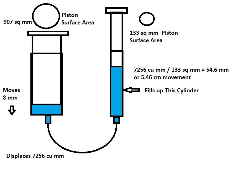
For my first experiment I worked from the other direction and pushed the large cylinder a short distance of 8 mm which extended the small cylinder a much longer distance of around 60 mm until it could not move any farther. I calculated this also which was off the first time but repeated trial proved that calculated and observed were very close.


For calculations we need the formula for the area of a circle :
Area of Circle = π x radius²
Large Piston cross section area = 3.14 x (34/2)² = 907 sq mm
Small Piston cross section area = 3.14 x (13/2)² = 133 sq mm
Moving the large piston 8 mm will displace amount fluid = cross section x length of movement
Fluid Displaced = 907 sq mm x 8 mm = 7256 cu mm
The movement of the small cylinder should be the fluid displaced / cross section area of small cylinder.
7256 / 133 = 54.6 mm movement of small cylinder
Actual movement was recorded at 60 mm or 6 centimeters. My calculations included some rounding errors and measurement of piston might not have been accurate.
I have not checked the amount of force generated but did check the amount required just to move the opposite cylinder. Moving the small cylinder with the large cylinder took a large amount of force, 1250 grams or around 12 newtons. This is like pushing down on the short end of a lever. Pushing the small cylinder took very little force.
Air Powered Model Car

I built the OWIKit Air Racer kit which uses compressed air to power the car much like how a steam engine functions. It is a rather difficult kit to build with so many pieces and the tiny O-rings. Blog article on building OWIKit Air Powered Racer.
Fantastic web site. Lots of useful information here. I am sending
it to several friends ans also sharing in delicious.
And obviously, thank you to your effort!
Superb
suprb!!!
The hydraulic crane is so fantastic but we need to do it in such a of moving as well rotating clockwise or anticlockwise.
People have done a lot more complicated syringe arms that could pivot in more directions, I was trying to keep it simple.
Bill Kuhl
I’ve been browsing online more than 3 hours today, yet I never found any interesting articles like yours. Personally, if all website owners and bloggers made good content as you did, the web will be a lot more useful than ever before.|
People have done a lot more complicated syringe arms that could pivot in more directions, I was trying to keep it simple.
a very thanks to Bill Kuhl
nice
Superb. I made with plastic toys
Famtabolus idea. I made with plastic toys
ur project is owsm ty for publishing it
i am also make same syringe hydraulic crane.
watch video : http://youtu.be/ysBgNp-rz_A
Very nice Niraj. Your unit is much more advanced than my simple one.
Bill Kuhl
thank you very much sir.
yeah but the basic principle of syringe mechanism is same
i am recent upload this new video must watch : http://youtu.be/IFKjYvZWbrw
Wow the parking system model you have created is amazing, my knowledge of electronics is not very extensive.
Bill Kuhl
this is very cool!!!!!!!!!!!!!!!!!!!!!!!!!!!!!!!!!!
thats right
Cool as
Cool as
good
Super ek dam fentastic ideas
thanks bro
May I know how much amount of milli gram weight does it lift with your syringes ……….
The syringes I used do not have a large difference in the diameter of the piston so there is not much of a mechanical advantage. The arm is not designed super sturdy so I would not try lifting too much weight with it.
Excellent!!! this is my next project in my school.
excellent to understand and given step-by-step.
It’s a nice device but very hard to make!!!!!
I tried to design this so that the wood used needed only a straight cut across. It would be best to use a drill press to get the holes straight. The wire pushrods need to be adjusted properly to get it close together properly.
Bill Kuhl
I love it! It is the coolest thing ever. I was trying to do another hydraulic arm and you inspired me! Well done!!!!!!!!!
how do you control the handles with syringes???
You grab the end of the syringe and either push it in or pull it out. One syringe raises or lowers the arm, the other one closes or opens the grabber part.
Its an awesome idea. I am working on it … Thanks for such a great idea.
Im still confused.. How to fill the water in the syringe?
The syringe has to be pushed in as far as possible with tubing connected. Put the other end in water and slowly pull back on syringe which should pull the water back. Try to block the end and then attach it to other syringe that is in the arm structure. Try to get as little air in the line as possible. Normally you need a few tries at this and pushing the air out.
Also I didn’t mention the water will be in a cup or a bowl. This is where the end of the tubing goes into and you suck it out from.
Ohh great … Thanks a lot , got it..!! 🙂
Just one word to say
awesome
Thanks, it would be nice if I had actual plans drawn but by following the steps and pictures plans are not really needed. This design uses pretty inexpensive materials and the wood cutting is straight cuts.
Bill
bravo fantastic buhat bakwaas laanet hai tujh pae
its an awesome project and also self explanitory
this is really cool
very good representation ,simple and understandable. thanks a lot…………….
V good. Thanks for the information. The 3rd picture after heading “aditional experiment”
The unit u wrote 9cm but the actual I feel is 9mm
I had the wrong picture, it has been replaced. Thank you!
This page was very informational. My Pre-engineering class doing a project similar to this. I found this page while doing research for it. We will be making robotic arms for a battle ball competition using a magnet and magnetic balls.
How do you manage to get all the air out of the syringe?
That is a good question I never seem to get it all out. I pull the water through and push the water very slowly until it is just about ready to push out end and then try to connect. Sometimes try this several times.
cool
good one, i liked it.
i would like to know in details of this device is it can work just like hand such as lifting,pushing,And what is the cost of this device.
Building a device like a hand would need many more movable joints, my device only has two. The cost in building my project is pretty low the major expense is the syringes which are normally found in packs of three. The wood used is cheap as well, my guess in building several of the projects the cost per device is a couple dollars.
Its superb
Its very good
fantastic,i like it,am also completing my project,I think on hydraulic fluid it would be better to use brake fluid rather than just water.keep it up
amazing
good
Can we use anothr liquid instead of water…
I have only tried adding food coloring to water so it was easier to see. No doubt other liquids would work.
Thnk u bill throuh your idea iam selectd for state level science exibition
its rly very helpful….thakxxxx
TThanks! I just came across this site and it answers so many questions for me. I have just returned to the classroom after about 15 years in administration. The Engineering/Technology lab that I have taken over is soooo out of date. Books and computers are over 16 years old. The module equipment is about the same age and have never been used/installed in the lab.
So I have been struggling to find info about the topics I need to teach. This site has helped so very much. Again, thanks for the great info!!
Thank you so much for your comments.
Sir Can u provide this in pdf form plz…its very helpful for me…
I added a link at the top of the article to download the PDF. Formatting isn’t perfect but I did take the advertising out.
Bill
this was helpful
this was a wonderful idea well done looks nice will make this and looks hard
most amazing thing in the world, even more amazing than the spider-man!!!
Can i know how to find pressure in the syringe..and how much weight it can lift..plz help me with these calculations bro..
I think an example for a 1″ diameter cylinder would work like this:
Hypothetical 1” diameter cylinder with 10 pounds of force acting down on it. What psi does this create and what would the force upward be created with an identical 1” diameter cylinder connected to the first cylinder?
Need the area of the piston using Area of a Circle = π x radius² 3.14 x .5² = .785 square inch
Figuring PSI 10 pounds x (1 square inch / .785 square inch) = 10 x 1.274 = 12.74 psi
Force = Pressure x Area = 12.74 psi X .785 sq in = 10 pounds of force
you have no life lol
coooooooooooooooooooooooooooooooooooooooooooooooooooooooooooooooooooool.
Niceeeeeeeeeeeeeeeeeeeeeeeeeeeeeeeee
Sir could u please tell me from where can i buy the kit for making this hydraulic lift.. please..
I do not sell anything but there is link on my website through Amazon to purchase Pitsco hydraulic arm kit.
very nic for studying physics as a game
excellent idea of hydraulic lift.
Thanks for the idea!!! We have thing called genius hour at school and we pick a project and we chose this one. Thanks again!!
great content thanks for posting. Jimmy
A friend and I are making this for a school project…we have not got very far yet but so far its working. I will make a new reply when we have the final product done!
A friend and I are making this for a school project. So far we are scetching this. Not sure how its going to work with the task we have to complete with it…But it had some good reviews so we decided to do this one.
mine is better
That is good, my design could use improvement. I was really trying to make it as cheap as possible with easy to find materials. On one I added a curved piece on the top of the bottom syringe.