
Background
Learning aerodynamics can get rather complicated quickly. To go along with the model airplane build articles I wanted to create an article that was not too complex but would be helpful to learn how to adjust the airplanes. Incorporating some math including basic trigonometry should show how the concepts can be put to practical use.
This tutorial is aimed at small free flight gliders and comparable rubber powered model airplanes such as the foam planes on this website but also simple balsa models as well.
I made an effort to make my simplified explanation accurate but that can be hard to do as even the experts seem to disagree. If you see any blatant mistakes be sure to leave a comment.
New : Math tutorial to help with sample problems.
Bill Kuhl
Surfaces of an Airplane

The three primary surfaces of most airplanes are the wing, stabilizer, and the vertical fin. There are also moveable control surfaces that will be covered later in this article.
The Wing Surface
The wing provides the primary lifting surface normally for an airplane with the stabilizer providing some lift but exists primarily to keep the wing in a relatively level position. There are planes that do not have a stabilzer but the rear of the wing curves upward to keep the wing level, this would be a “flying wing” configuration.

Wing Loading
An important factor in the performance is the “wing loading”. That is how much weight is supported by the wing area in units such as grams per square inch or grams per square centimeter, larger aircraft would use larger units. The units for wing loading would then be ounces per square inch or grams per square centimeter.
Increasing the surface area of the wing will decrease the wing loading except that the weight of the larger wing will be greater as will the drag.

Calculate Wing Loading for Sample Wing
Wingspan 12” Wing Chord 3” = Wing Area?
Sample Weight 10 Grams Wing Loading = Weight / Wing Area What is the wing loading?
Don Ross in his book Rubber Power Models stated for small airplanes a good wing loading is .33 grams per square inch. Does this sample wing meet this criteria?
Lift
Exactly how lift is created on the wing of an airplane is still a topic that is not agreed upon by all who study aerodynamics. Traditional theory was that because of the curved surface on the top of the wing, this created a longer path than the flat surface of the bottom of the wing creating a lower pressure on the top surface causing the wing to be sucked upward. Lower pressure on the top of the wing is part of the lift components but not because of the shape difference between the upper and lower surfaces. Many shapes of wings will lift an airplane; flat wings, wings curved the same on the top and bottom (symmetrical) or concave bottom surface wings. Flat or symmetrical wings do need the wing surface to be angled upwards (positive angle of attack) while some wing airfoil types will start to lift at zero degrees or less.
More recent theory of lift is that both the air pushing on the bottom of the wing and deflecting downwards and the lower pressure above the wing contribute to the total lift. The most efficient types of wings will create the lift needed to support the airplane weight while creating less drag. For simple model airplanes, a flat wing might be acceptable for ease of construction.

Air flows over and under wing in flight.
A Few Basic Airfoil Types

Note Clark Y is a common airfoil in the type of airfoil that is curved on the top and flat on the bottom. It has been pointed out that the Clark Y is not perfectly flat on the bottom. I am trying to relate a typical airfoil that is curved on the top and flat on the bottom.

The Angle of Attack (AOA) is the angle of the wing as it relates to the relative wind. This is Not the same as the incidence angle.
Incidence and Decalage

Incidence angle is the angle between chord line and longitudinal axis.

Decalage is the difference in the incidence angle between wing and stabilizer. Commonly there will be 2 – 3 degrees difference with the wing being at the higher incidence.

It is possible for airplanes to fly with no decalage at all this is the “0 – 0” setting used on some hand launch gliders. This helps in the high-speed launch phase but sometimes the plane will not recover from an upset and crash.
Note: even with no decalage the plane still flies through the air with some positive incidence. Frank Zaic had said that a free flight airplane trimmed for a floating glide will normally fly at around 6 degrees angle of attack. There is also a “downwash” from the wing that changes the effective angle of the stabilizer.
Additional Note: the angles of incidence work together with the balance point of the airplane – Center of Gravity which will be discussed later.
Three Axis of Motion of an Airplane
* Pitch (Lateral Axis) climb and dive motion
* Roll (Longitudinal Axis) bank left or right motion
* Yaw (Normal Axis) nose pivots to the left or right
It is important to know the three axis that an airplane pivots to be able to analyze the flight path and be able to perform trim adjustments.
Providing Thrust by With a Rubber Motor

The rubber motor can be wound by using index finger along one blade of the propeller and spinning the propeller in a clockwise direction.

Mechanical winder is much faster method to wind rubber motor. The motor can be stretched out at least 2 to 3 times the normal length and then more turns can be wound in as you come back to rear motor hook.
Propellers
Propeller is like rotary wings that pull the aircraft through the air, most common is to have two blades but other combinations of blades or even a single blade have been tried.
Propeller has a diameter which is the length from tip to tip but it is called the diameter as the tips are going around a circle.

The propeller has a pitch which is defined as the distance the propeller would advance forward in one complete revolution if there were no slippage. Normally the pitch is measured by putting the propeller on a flat surface and measuring the angle at a certain spot along the propeller typically about ¾ from the center. The blade angle along the propeller normally increases and then decreases again to almost no angle at the tip. Typical also is a curve in the front of the propeller blades and the back of the blades are flat or curved which creates a more efficient airfoil but flat blades set an angle will work but not as efficiently.

Normally for the specifications of the airplane the propeller will be matched up in diameter and pitch but for the simple model airplanes we will size the airplane around a pre-made propeller that is 5 ½” to 6” in diameter.
The Rubber Motor
The wound rubber strip motor supplies an amazing amount of energy for it’s weight. Plastic propellers assemblies are available that easily slide over the balsa motor stick and should provide sufficient thrust to fly model airplane with wingspans from 10” – 16” provided the airplane is light enough and properly designed. For this tutorial plastic propellers of 5 ½” to 6” diameter will be considered, rubber strip that is either 3/32” or 1/8” wide.
Some Basics of the Rubber Motor
The thinner the rubber motor is the more turns that can be wound into it but the less energy that will be returned.
Most of the energy will be released in the first few seconds, the power burst and then it will gradually decrease for most of the run.
Descend, Glide or Dive
When an airplane is not maintaining altitude or climbing it is descending, diving or gliding. If the airplane does not create sufficient lift for the weight or the nose has been pointed downward because some type of an upset such as a stall or elevator surface was deflected down the airplane will fly towards the ground.
Gliding is when there is no thrust propelling the airplane other than the force of gravity that pulls it down the glide angle.

Gliders

Simple gliders referred to in this article are launched with a gentle hand toss which gives the glider kinetic energy. The glider is also pulled down the glide slope by the force of gravity.
Trigonometry can be used to compute the amount lift and the drag amount in a glide. In the Simple Glider Curriculum Gary Hinze created which also appears on this website, Gary presented a method of computing these amounts by using ratio. On a NASA website formulas were presented to compute lift and drag in a glide that required solving for several variables, Gary pointed out the formulas are really as simple as this:
Glide Angle = (Height / Distance) Arctangent
Lift = Weight x Cosine(Glide Angle)
Drag= Weight x Sine(Glide Angle)
Note: the calculator built into Windows can do trig functions by changing the View to Scientific. Arctangent function is obtained by pressing Inv button and then using Tan¯ᶦ.
Calculate the glide angle if launched from a height of 1 meter and glider travels over 5 meter distance?
What would the lift be if the weight was 10 grams?
What would the drag be?
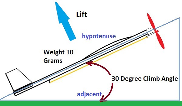
The Climb of an Airplane
The climb of an airplane might be more confusing that it would first appear. To start when lift is greater than the weight of the aircraft the nose begins to pitch upwards. As the thrust, created by the spinning propeller pulls the airplane at an increasingly steeper angle the amount of lift actually decreases as more of the force is coming from the pull upwards. When the airplane is completely vertical in the hover position there is no lift from the wing.
In the formula for lift the cosine of the climb angle is multiplied by the weight. As the angle increases the value returned from the cosine function decreases. The thrust formula contains the sine function which increases as the climb angle increases.

Climb – front of the plane is moving up in pitch axis.
Lift = Weight x Cosine Angle of Climb
Thrust = Drag + (Weight x Sine of Angle of Climb)
For a weight of 10 grams and angle of climb 20 degrees, calculate lift and thrust?
In a constant climb the forces are return to equilibrium, but now thrust + lift = drag + weight.
Downthrust and Sidethrust
There are a couple of thrust adjustments used with powered model airplanes that can be used to help a couple of undesirable as characteristics of flight.
Downthrust is tilting the thrustline a small amount downwards. This works well with the power burst aspect of the rubber motor when there is excessive thrust to start the flight causes too steep of climb, the downthrust will tend to pull the nose downward but as the thrust decreases the pull down will be less. By this point the climb should have levelled off which is when less downward pull is needed. The plastic nose bearings normally have some downthrust built in.
Sidethrust is normally tilting the thrustline to the right to compensate for the tendency of the propeller torque to pull the airplane to the left when viewed from the rear.


Stall Condition

At some angle of attack the air flowing over the rear portion of the top of the wing detaches and becomes turbulent, the wing loses lift.
Pitch – Lateral Stability

The Center of Gravity (CG) is the point where the weight forces are concentrated. This will always be specified on model airplane plans.
Center of Pressure

The Center of Pressure will move forward and back during flight based on the angle of attack of the wing. Further ahead for greater angle of attack.
Understanding the Moment Arm

To understand the “moment arm” the workings of the simple machine the lever is needed. When there is a distance in length between the sides of a pivot point or “fulcrum” there will be a mechanical advantage. The longer side will move farther vertically than the short side of the fulcrum but more force will be applied on the shorter side.
Moving a lever around a pivot point or axis is producing a “torque”. The formula for torque is force multiplied by distance, this distance is the moment arm.

The “tail moment arm” length in the pitch axis is defined as the distance between center of gravity of the wing and the aerodynamic center of the stab.
Note: this is the definition given by many sources. Another source defined “the tail moment arm as the distance between the mean aerodynamic chords of the wing and the stab.”
The amount of force needed on the stabilizer varies with length of the moment arm. With a longer moment arm a smaller stabilizer can be used which should create less drag.
Pitching Moment of an Airfoil

To further complicate matters, airfoils except symmetrical and reflexed airfoils have a “pitching moment” which is a force twisting the front of the wing downwards.

With a long moment arm if the tail surface are not lightweight it can take a lot of weight in the nose for proper center of gravity balance. The surface area is more effective with a longer moment arm in stabilizing the airplane so less surface area is needed.

The AMA Cub rubber powered airplane has a short moment arm but the stabilizer area is large to give it more force to stabilize the airplane in pitch.
Recovering from a Dive Without Control Surface Deflection

As the plane goes into a dive the speed will increase. This will increase the lift causing the wing to pull up and at the same time the force pushing down on the stabilizer will be greater pushing down with more force causing the nose to pivot upwards.
Controlling the Flight Path
Full-scale aircraft and radio controlled model aircraft adjust the flight path by control surfaces. Free flight model aircraft often use “trim tabs” to adjust the flight path using a set deflection of the control surface. More complicated free flight models can have control surfaces that move in flight but without control from a pilot on the ground.
Control Surfaces Added to Flying Surfaces


Elevator Movement Up and Down as Seen From Side View

Rudder Movement Right and Left as Seen From Above
Dihedral

Dihedral is the mechanism to level the wing when it pivots on the roll axis into a banked position. When the rudder is deflected starting the yaw with dihedral the side slip will start advancing into a bank.
Turning the Airplane
An airplane normally will be in a bank condition where one wing tip is higher than the other as viewed from the front or the rear. Turning the airplane with the rudder will cause the airplane to turn in the normal axis which is known as “yaw”.
If the airplane does have dihedral the yaw will start a side slip causing the bank angle needed for a turn.
Yaw – Normal Axis

Yaw is when the nose of the airplane moves to the left or right pivoting on the Center of Gravity. Normally a deflection of the rudder will cause this. To cause a proper banked turn with only rudder normally dihedral is needed.
Vertical Fin
To keep the airplane flying straight normally a vertical fin is needed, the position is usually above the horizontal stabilizer. Like the stabilizer the moment arm somewhat dictates the area required of the vertical fin.

For a sport rubber model 10% of the wing area is good proportion to try. What would be the area for the vertical fin using the 36 square inches of wing area? After computing the square inches of the vertical fin, what function would you use on this area to get equal length sides?

The easiest method for me was to double the area of the missing triangle is to put two triangles together. 1.35 sq. in. x 2 = 2.7 sq. in. Divide this by 1.5” = 1.8“ for the bottom side. Check this out: 1.5” x 1.8” /2 = 1.35 square inches
Putting the Triangle and Square Together for Entire Vertical Fin

Turning A Plane With Dihedral With the Rudder

With dihedral the yaw motion will start a side slip to the outside of the turn and the outside wing will lift more causing the plane to bank.
The Airplane Banks as Result of Start of Yaw Motion

Longitudinal or Roll Axis

Banking Due to Aileron Deflection
Aileron controls move in opposite directions to cause the wing and the airplane to bank in roll axis.
Lift Reduced as Plane Flies in a Circle
The lift of the plane is reduced as it flies in a circle, the smaller the circle the greater the reduction in lift. Free flight airplanes will normally be adjusted to circle to reduce the area the flight will cover. Increasing the amount of turn is a trimming technique often used if there is too much climb.

Maintaining altitude in a turn the vertical component of the lift must be equal to the weight of the airplane. The amount of lift required will be the vector resultant of the vertical and horizontal components. In physics the horizontal component is known as the “centripetal force”. The confusing part is that centripetal force points towards the inside of the circle. Centrifugal force is the force directed in the opposite direction but this has been called a “false force”.
Centripetal Force

A common example of centripetal force has been to swing a ball around on a string. The force directed outwards 90 degrees from the centripetal force is the labeled as the velocity. Realize that these two forces are constantly moving around the circle with the string and ball. If the string were released it would follow the velocity direction.
Another confusing fact to remember is that even if ball is moving at a constant speed it is always accelerating because the direction is constantly changing. The acceleration is directed towards the center of the circle.
Note: source of this information is Wikipedia Article Centripetal Force, there has been dispute on the labeling of this diagram, if you know a better source send a comment.
Formulas Used in Forces in a Turn
Centripetal Force = mass x velocity ² / radius
Lift = weight / cosine (bank angle)
Calculate the lift if the weight is 10 grams and bank angle is 20 degrees?
Additional Information
Endlesslift Blog – very good articles on beginner model aviation topics.
The National Free Flight Society – “The National Free Flight Society is the only organization in the United States that serves the interests of all free flight categories. The Society was formed over 30 years ago to promote free flight activities and continues as a vital, growing organization dedicated to the advancement of the free flight hobby and sport. ”
Academy of Model Aeronautics – the largest model aircraft organization in the world.
AMA Flight School – excellent educational resource for all things model aviation.
Join My Facebook Group for Simple Foam Free Flight Airplanes
Additional Math Related Blog Posts
Torque and Lever Arm Calculations for Mousetrap Cars
Proving Pascal’s Principle With Syringe Hydraulics
Using Online Calculator to Compute Lift
Experimenting with NASA Foilsim Website
Finding Height Using Estes AltiTrak
Nice content and thorough treatment of all topics relating to rubber band powered planes. Keep up the good work!
Very good. Answers lots of first timer questions. Keep it up!!!
Randy
There’s a good balance between clarity and thoroughness here. I’m looking forward to the further development of this promising learning resource.
Nice work here Bill!
Hi Bill, When I taught after school model airplane activities, I could have used this tool as an introduction to gliding and rubber power. Nice work. Someone out there could use this as part of a science lesson plan on beginning aerodynamics.
Very good , the art work helps get the idea across about the control surfaces
and the formulas give the science and math principals for all of them !!
George
Very informative!
Could you please add details about these points or explain to me (or provide links)?
1. Pitching moment of airfoil (I had recently build a small hand launched card paper and popsicle stick model of Wright 1903 Flyer, 20.5cm wingspan and 3.3cm chord, and without any propulsion; it was flat wing and flew 12-14 feet or so. I thought I will make a cambered wing and see the difference but it always dived down. The front elevator was probably too small to counter the dive. People on Hip Pocket Forum told me that the camber is a bit too much for the small chord- they said it should be max 4% whereas mine was a little more than 10%…reducing the camber further with such small dimensions meant more or less a flat wing)
2. Aerodynamic centre
3. Centre of Pressure
4. Why some plans show ’tilting the stabilizer a little to the right’
(I couldnt find about these points on Endless Lift)
People on Hip Pocket are probably more knowledgeable than I. Towards the bottom on my website page Foam Plate and Plastic Straw Gliders is a picture of a simple canard glider. I know the airfoil camber was less than 10% which is way too much. The little canard wing needs some positive incidence in front. Somewhere a small Wright glider made from foam and plastic is sold, I use mine in demonstrations about aviation history.
Tilting the stabilizer is done to give turn to the glide and not the power phase of a flight.
I am entrusted to this. detail information /calculation